


Voice over Internet Protocol (VoIP) refers to any technology that delivers voice communications over IP networks instead of traditional circuit-switched telephone lines. Common voice over internet protocol examples include SIP-based enterprise phone systems, RTP media streams carrying audio packets, and WebRTC softphones running inside web browsers. VideoSDK extends these concepts by providing developer-friendly real-time communication SDKs that handle WebRTC media transport, SIP integration, and AI-powered voice agents across ten or more platforms.
Building a real VoIP system means understanding how signaling, media transport, and network configuration work together. Reading protocol specifications gives you the theory, but working through concrete voice over internet protocol examples shows you what actually happens when a phone rings, a packet drops, or a firewall blocks audio in one direction. This guide walks through several practical examples that developers and network engineers encounter in production environments.
You will see how an enterprise VoIP network is structured using VLANs and DHCP options, how a SIP call flows from INVITE to ACK, how RTP carries voice media across the network, how WebRTC softphones replace traditional SIP stacks in browser-based applications, and how to troubleshoot the most common issues that arise. By the end, you will have a clear mental model of how these pieces fit together and where modern SDKs like VideoSDK simplify the implementation path.
Voice over Internet Protocol (VoIP) Examples: An Overview
Voice over Internet Protocol examples span a wide range of implementations, from small office phone systems to global enterprise networks handling thousands of concurrent calls. Each example demonstrates a different layer of the VoIP stack, including signaling protocols that set up calls, media transport protocols that carry voice packets, and network infrastructure that prioritizes voice traffic over data.
Developers learning VoIP benefit from studying examples because the protocol interactions are inherently multi-system. A single phone call might involve a SIP registrar, a media gateway, a NAT traversal mechanism, a quality-of-service policy on a router, and a firewall rule allowing UDP traffic on specific ports. Each of these components must work correctly for the call to succeed.
The examples in this guide progress from infrastructure-level configurations to application-level implementations. You will start with an enterprise network topology using Cisco Packet Tracer concepts, move through SIP signaling sequences, examine RTP media transport details, explore a modern WebRTC softphone architecture, and finish with troubleshooting scenarios that engineers face regularly. VideoSDK appears in the WebRTC and SIP integration sections as a practical way to implement these patterns without building the underlying transport layer from scratch.
Enterprise VoIP Network Example Using Cisco Packet Tracer
Enterprise VoIP networks combine traditional networking concepts with voice-specific configurations to deliver reliable phone service across an organization. This example describes a typical setup that network engineers build when constructing a VoIP infrastructure for a medium-sized business.
Network Topology Overview
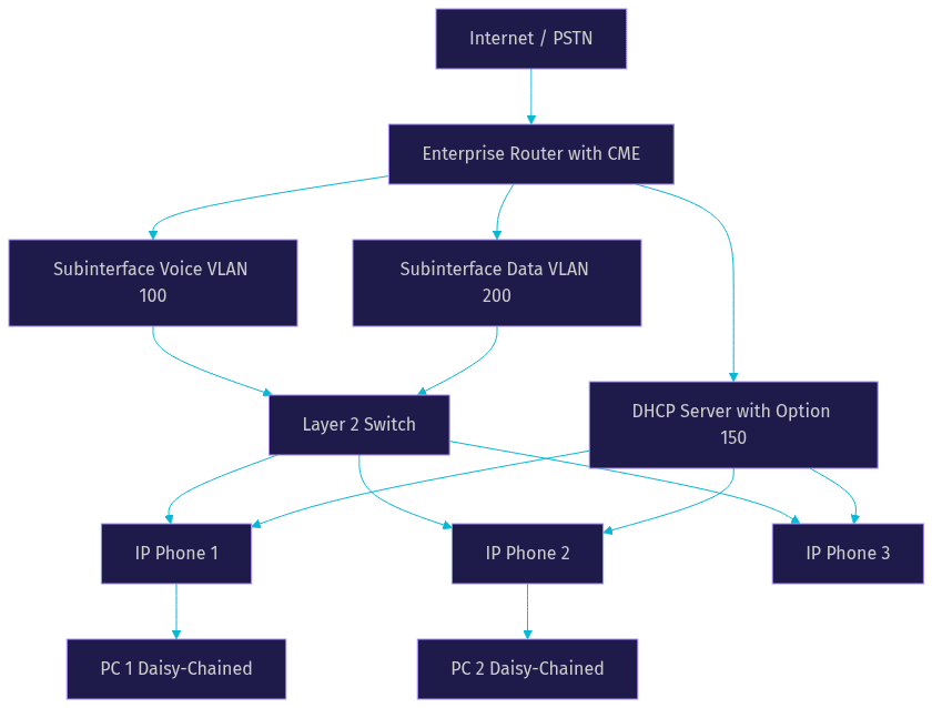
A standard enterprise VoIP topology includes a central router configured as a router-on-a-stick to handle inter-VLAN routing, one or more layer-2 switches connecting end devices, separate VLANs for voice and data traffic, and IP phones connected to the switches alongside PCs. The IP phones typically have a built-in switch port that allows a PC to daisy-chain through the phone, so a single wall jack serves both devices while keeping voice and data traffic logically separated.
The router connects to the PSTN through a SIP trunk or a traditional digital voice port, depending on the deployment. Internally, the router runs Call Manager Express (CME), which acts as the call processing engine for the IP phones. Each phone receives its configuration from the CME service, registers with the router using SIP or SCCP, and places calls through the router's dial-plan. The switch ports connecting IP phones are configured as access ports with a voice VLAN assignment, ensuring that voice packets are tagged with the correct VLAN identifier while data packets remain untagged.
VLAN and DHCP Configuration Example
Voice VLAN separation is critical for quality of service. By placing IP phones on a dedicated VLAN, network engineers can apply QoS policies that prioritize voice traffic over data traffic during periods of congestion. The voice VLAN typically uses a different subnet than the data VLAN, and the router's subinterfaces handle routing between them.
DHCP plays a central role in VoIP deployments because IP phones need to discover their TFTP server to download configuration files. DHCP option 150 is the standard mechanism for pointing IP phones to the TFTP server where their firmware and configuration reside. When a phone boots, it sends a DHCP request on the voice VLAN, receives an IP address along with option 150, and then contacts the TFTP server to retrieve its configuration profile. Without option 150, phones cannot find their configuration server and will fail to register.
Call Manager Express (CME) Setup Example
Call Manager Express is Cisco's router-based call processing solution for small to medium deployments. In this example, the router running CME serves as both the DHCP server for the voice VLAN and the SIP registrar for the IP phones. The CME configuration defines the maximum number of phones and directory numbers supported, creates ephone-dn entries that represent phone extensions, and associates those extensions with specific phone MAC addresses.
Dial-peers form the routing layer of the CME system. A dial-peer is a routing rule that tells the router where to send a call based on the dialed digits. For internal calls, a dial-peer points to a local extension. For external calls, a dial-peer points to the PSTN gateway or SIP trunk. In a multi-site deployment, additional dial-peers route calls over a WAN link to remote sites by matching destination patterns and forwarding the call to the remote router's IP address.
The following diagram illustrates the router-on-a-stick architecture with voice and data VLANs, IP phones, and the CME call processing engine.
SIP Call Setup Example: Step-by-Step Walkthrough
The Session Initiation Protocol (SIP) is the most widely used signaling protocol in modern VoIP systems. Understanding a SIP call flow example is essential for debugging registration issues, call setup failures, and routing problems. This section walks through the three core SIP interactions that every VoIP engineer should recognize.
SIP INVITE Flow
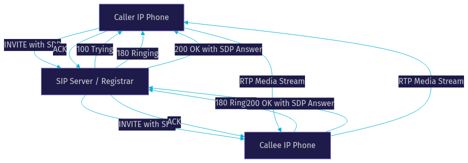
A SIP call begins when the calling party sends an INVITE message to the called party through one or more SIP servers. The INVITE message contains critical headers that define the call parameters. The From header identifies the caller, the To header identifies the intended recipient, the Call-ID header provides a unique identifier for the call session, and the Session Description Protocol (SDP) body describes the media capabilities of the caller, including codec preferences, RTP port numbers, and media types.
When the called party receives the INVITE, it responds with a 100 Trying message to acknowledge receipt, followed by a 180 Ringing message to indicate that the destination phone is alerting the user. Once the user answers, the called party sends a 200 OK message containing its own SDP answer, which finalizes the codec selection and RTP port assignments. The calling party then sends an ACK message to confirm that it received the 200 OK. At this point, the SIP signaling phase is complete and RTP media flows directly between the two endpoints.
SIP Registration Example
Before an IP phone can place or receive calls, it must register with a SIP server. The registration process begins when the phone sends a REGISTER message to the SIP registrar, containing the phone's SIP URI in the To header and the registrar's address in the Request-URI. The registrar typically challenges the phone with a 401 Unauthorized response, prompting the phone to resend the REGISTER with authentication credentials in an Authorization header.
Once the registrar validates the credentials, it responds with a 200 OK and stores the binding between the phone's SIP URI and its current IP address. This binding allows the registrar to route incoming INVITE messages to the correct phone. Registrations expire periodically, and phones send fresh REGISTER messages before the expiration time to maintain their binding. If a phone loses connectivity, its registration eventually times out and the registrar stops routing calls to it.
SIP Call Routing with Dial-Peers
In a multi-site VoIP deployment, SIP call routing relies on dial-peers to match dialed digits and forward calls to the appropriate destination. A dial-peer configured for a remote site matches a destination pattern, such as a four-digit extension range, and points to the remote router's IP address as the session target. When a user dials an extension that matches the remote pattern, the local router sends the INVITE to the remote router, which then routes the call to the destination phone.
The following diagram shows a simplified SIP call flow between two endpoints through a SIP server, including the INVITE, 100 Trying, 180 Ringing, 200 OK, and ACK exchange.
RTP Media Transport Example
While SIP handles call signaling, the Real-time Transport Protocol (RTP) carries the actual voice media. RTP runs over UDP and is designed for real-time data delivery where low latency matters more than guaranteed delivery. Understanding RTP is essential for diagnosing audio quality issues in any VoIP system.
RTP Packet Structure
Every RTP packet contains a fixed header followed by the media payload. The header includes several fields that receivers use to reconstruct the audio stream correctly. The payload type field identifies the codec used for the media, such as G.711 for uncompressed voice or Opus for modern low-bandwidth audio. The sequence number increments by one for each packet sent, allowing the receiver to detect lost packets and reorder packets that arrive out of sequence.
The timestamp field reflects the sampling instant of the first byte in the payload, and it advances based on the codec's sampling rate rather than wall-clock time. This allows the receiver to play back audio at the correct pace and detect jitter, which is the variation in packet arrival times. The synchronization source (SSRC) identifier uniquely identifies the source of the stream within a session, and multiple SSRCs can coexist in a single session for conferencing scenarios.
QoS and Bandwidth Considerations
RTP streams are sensitive to network conditions because UDP provides no retransmission or congestion control. Quality of Service policies address this by marking voice packets with a high-priority DSCP value, typically Expedited Forwarding, so that routers and switches prioritize voice traffic during congestion. Bandwidth calculations for VoIP depend on the codec, packetization period, and layer-2 overhead. A G.711 call using 20-millisecond packetization consumes approximately 87 kilobits per second including RTP, UDP, and IP headers, while an Opus call at a lower bitrate might use only 24 kilobits per second.
Network engineers must account for this bandwidth on every link in the call path, especially on WAN connections where voice traffic competes with data. VideoSDK addresses these challenges at the application layer by implementing network-adaptive streaming that automatically adjusts bitrate and resolution based on real-time bandwidth detection, reducing the need for manual QoS tuning in many deployment scenarios.
Monitoring RTP Streams
Monitoring RTP streams involves capturing packets and analyzing key metrics including packet loss, jitter, and round-trip time. Tools like Wireshark can decode RTP streams and display statistics that reveal whether quality issues stem from network congestion, codec mismatches, or timing problems. The RTP Control Protocol (RTCP) runs alongside RTP and provides periodic reports on stream quality, including packet counts, loss rates, and jitter measurements, which monitoring systems aggregate to generate MOS scores and quality dashboards.
Softphone Implementation Example with WebRTC
Modern VoIP applications increasingly use WebRTC instead of traditional SIP stacks to deliver voice communication directly in web browsers and mobile apps. This example describes how a WebRTC softphone works and how it connects to traditional telephony infrastructure through a gateway.
WebRTC Peer Connection Overview
WebRTC is a browser-native real-time communication protocol that handles media capture, encoding, NAT traversal, and secure transport without requiring plugins or standalone applications. A WebRTC softphone begins by accessing the user's microphone and speaker through browser APIs, then creates a peer connection object that manages the media session. The peer connection negotiates codecs, establishes a secure DTLS connection, and uses ICE (Interactive Connectivity Establishment) to find the best network path between endpoints.
Unlike SIP, which requires a dedicated signaling server and client-side SIP stack, WebRTC handles media transport natively in the browser. Signaling in WebRTC is flexible because the specification does not mandate a specific signaling protocol. Developers typically use WebSockets or HTTP-based protocols to exchange SDP offers and answers between peers before the peer connection takes over media delivery. VideoSDK's video calling SDKs build on this foundation by wrapping WebRTC complexity into simple SDK methods that handle room creation, participant management, and media stream routing across React, React Native, Flutter, Android, iOS, and JavaScript applications.
Integrating a SIP-to-WebRTC Gateway
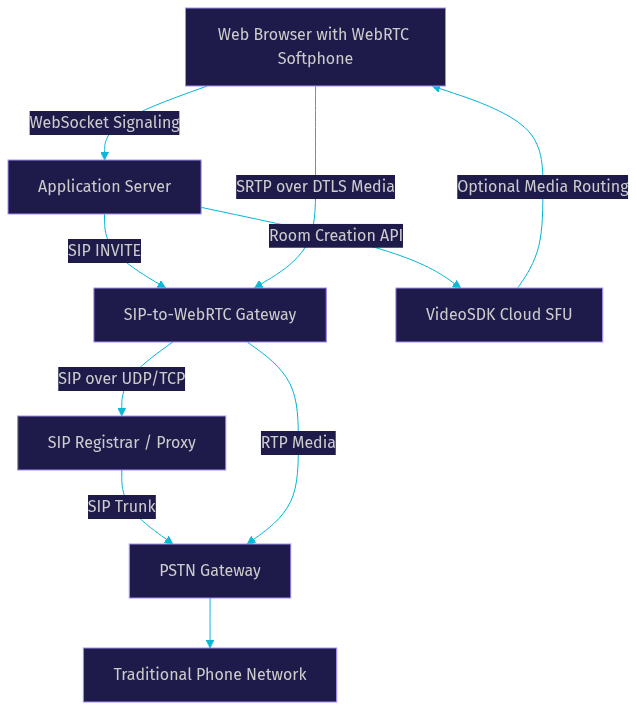
A pure WebRTC softphone can call other WebRTC endpoints but cannot directly reach PSTN numbers or legacy SIP phones. A SIP-to-WebRTC gateway bridges this gap by translating between WebRTC media and SIP signaling on the server side. When a WebRTC user dials a PSTN number, the gateway receives the call request over the web signaling channel, converts it to a SIP INVITE, and forwards it to a SIP trunk or PSTN gateway. Media flowing from the WebRTC side uses SRTP over DTLS, while media on the SIP side may use plain RTP or SRTP depending on the trunk configuration.
VideoSDK provides built-in SIP and telephony integration that handles this bridging automatically. Developers can connect traditional SIP trunks from providers like Twilio, Vonage, or Telnyx to VideoSDK rooms, allowing web-based participants and phone-based participants to join the same call. The gateway handles DTMF events, call transfers, and codec translation without requiring developers to build and maintain the bridge infrastructure themselves.
User Experience Walkthrough
From the user's perspective, a WebRTC softphone feels like a web application rather than a traditional phone. The user opens a browser page, grants microphone permission, and sees a dial pad or contact list. When they dial a number, the application sends the call request to the server, which initiates the SIP leg through the gateway. The user hears ringback tones generated locally or streamed from the gateway, and when the far end answers, the audio path connects through the peer connection.
Incoming calls appear as visual notifications in the browser, and the user can accept or reject them with a click. Call waiting, hold, and transfer are handled through UI controls that send corresponding SIP messages through the gateway. VideoSDK's Prebuilt UI Kit provides a drop-in interface for this experience, letting developers embed a working calling interface with minimal configuration.
The following diagram shows the architecture of a WebRTC softphone connected to the PSTN through a SIP gateway.
Common Issues and Troubleshooting in VoIP Examples
Even well-designed VoIP systems encounter problems. This section covers the three most common issues that engineers face when deploying and maintaining voice over internet protocol examples in production environments.
Registration Failures
Registration failures occur when an IP phone cannot complete the SIP REGISTER exchange with its registrar. The most common cause in enterprise deployments is a missing or incorrect DHCP option 150 configuration, which prevents the phone from locating its TFTP server and downloading its configuration file. Without the configuration, the phone does not know the registrar's address and cannot attempt registration.
Other causes include incorrect SIP credentials, firewall rules blocking SIP signaling traffic on port 5060 or 5061, DNS resolution failures for SIP domain names, and certificate mismatches on TLS-secured SIP trunks. Troubleshooting registration failures starts with verifying that the phone received the correct DHCP options, then checking network connectivity to the registrar, and finally examining SIP message logs to identify where the registration exchange breaks. Authentication failures typically appear as repeated 401 Unauthorized responses without a subsequent successful 200 OK.
One-Way Audio
One-way audio is the symptom where one party can hear the other but not vice versa. This is almost always a network path issue rather than a signaling problem, because SIP signaling completed successfully for the call to connect. The root cause is typically a firewall or NAT device that blocks RTP media traffic in one direction.
In NAT scenarios, the SIP INVITE carries the private IP address of the sender in its SDP body, and the remote endpoint attempts to send RTP to that private address, which is unreachable across the internet. SIP Application Layer Gateways (ALGs) on firewalls can sometimes resolve this by rewriting SDP bodies, but ALGs are notoriously unreliable and often introduce more problems than they solve. Session Border Controllers (SBCs) provide a more robust solution by anchoring the media path and ensuring that RTP flows symmetrically through a single public IP address. VideoSDK's cloud infrastructure handles NAT traversal automatically through its SFU architecture, eliminating one-way audio issues for WebRTC-based calls.
Call Quality Degradation
Call quality degradation manifests as choppy audio, robotic voice artifacts, dropped words, or noticeable delay. These symptoms stem from three primary network impairments: jitter, packet loss, and latency. Jitter is the variation in packet arrival times, and while jitter buffers in the receiving endpoint can compensate for small variations, excessive jitter causes buffer underruns and audio gaps.
Packet loss directly removes audio segments from the stream. Loss rates above one percent become noticeable to users, and rates above five percent render calls unusable. Latency above 150 milliseconds one-way creates a walkie-talkie effect where callers talk over each other. Diagnosing quality issues requires measuring these metrics using RTCP reports or network monitoring tools, identifying the network segment where impairment occurs, and applying QoS policies or increasing bandwidth on the affected link. VideoSDK mitigates these issues through network-adaptive streaming that adjusts media parameters in real time based on detected network conditions.
Definitions Glossary
SIP (Session Initiation Protocol): A text-based signaling protocol used to establish, modify, and terminate VoIP call sessions. SIP handles call setup, registration, and routing but does not carry voice media itself.
RTP (Real-time Transport Protocol): A network protocol that delivers audio and video media over UDP with sequencing, timestamping, and payload type identification. RTP carries the actual voice packets in a VoIP call.
Dial-Peer: A routing rule in a VoIP system that matches dialed digits to a destination, such as a local extension, a remote site, or a PSTN gateway. Dial-peers are fundamental to call routing in Cisco CME and similar platforms.
DHCP Option 150: A DHCP configuration option that provides IP phones with the address of their TFTP server, allowing them to download configuration files and firmware. Without option 150, IP phones cannot bootstrap themselves on the network.
WebRTC: A browser-native real-time communication technology that handles media capture, encoding, NAT traversal, and secure transport without plugins. VideoSDK builds its SDKs on WebRTC foundations to deliver cross-platform voice and video calling.
SIP-to-WebRTC Gateway: A server component that translates between SIP signaling and WebRTC media, enabling browser-based softphones to place and receive calls through traditional telephony infrastructure.
Key Takeaways
- Voice over internet protocol examples span infrastructure configurations like VLANs and DHCP option 150, signaling protocols like SIP, and media transport protocols like RTP, each addressing a different layer of the VoIP stack.
- SIP call flows follow a predictable INVITE, 100 Trying, 180 Ringing, 200 OK, and ACK sequence, with SDP bodies negotiating codec and port assignments between endpoints.
- RTP carries voice media over UDP using sequence numbers, timestamps, and payload type fields that receivers use to reconstruct audio and detect quality impairments.
- WebRTC softphones replace traditional SIP stacks in browser-based applications, and SIP-to-WebRTC gateways bridge these softphones to PSTN and legacy SIP infrastructure.
- VideoSDK simplifies VoIP implementation by providing WebRTC-based SDKs across ten or more platforms, built-in SIP and telephony integration, network-adaptive streaming, and a Prebuilt UI Kit for zero-code embedding.
Conclusion
Working through voice over internet protocol examples from enterprise network topologies to SIP call flows, RTP media transport, and WebRTC softphone architectures gives you a complete picture of how modern voice systems operate. Each layer builds on the previous one, and understanding the interactions between signaling, media, and network infrastructure is what separates a working deployment from a broken one.
If you are building a voice or video calling application, VideoSDK handles the hardest parts for you. The SDKs manage WebRTC peer connections, NAT traversal, codec negotiation, and network-adaptive streaming across React, React Native, Flutter, Android, iOS, JavaScript, and other platforms. The built-in SIP and telephony integration connects your web and mobile users to traditional phone networks without requiring you to build and maintain a gateway. You can explore the VideoSDK documentation to get started, browse code samples for practical integration patterns, or join the VideoSDK Discord community to ask questions and share what you are building. Sign up at app.videosdk.live/login to claim your free credits and start building today.
What are you building with VoIP or WebRTC? Drop a comment below, I would love to hear what kind of voice over internet protocol use case you are working on.
Conclusion: The Expanding Role of VoIP
VoIP has moved from a niche, cost-saving alternative to a foundational technology for modern communication. The diverse voice over internet protocol examples discussed – from personal apps like WhatsApp and Skype to enterprise solutions like Microsoft Teams and critical industry applications in healthcare and education – demonstrate its versatility and widespread impact. For developers, understanding VoIP provides opportunities to build powerful, integrated communication features into the next generation of applications. Its evolution continues, promising even richer and more seamless ways to connect using the internet.
Free $20 Balance for AI Voice Agents & Video Calls
FAQ